
The following is part one of a series of 3 blogs that will go through a white paper written by New Era Converting Machinery’s John A. Pasquale III. The white paper is titled “Principles and Uses of Roll Coating Equipment.”
Part 1 will offer an abstract and introduction to the blog series, as well as an in depth look at direct gravure coating. Part 2 will examine both reverse gravure coating and differential offset gravure coating. Part 3 will wrap the series up with an explanation of reverse roll coating and offer a brief conclusion.
—–
Part 1: Abstract, Introduction and Direct Gravure Coating
ABSTRACT
By understanding the operating features of gravure and reverse roll coaters, the converter can make an informed decision when selecting a roll coating manufacturing process. Recognizing that substrates can often be coated by more than one method, attention must be paid to the characteristics of each coater to ensure success using the method chosen. The expected result should be the use of the most cost-effective coating technique that will produce an acceptable end product.
INTRODUCTION
A presentation of various roll coating methods including Direct/Reverse/Differential Offset Gravure and Reverse Roll coaters. The basic concepts of each method, why and when they are used and the advantages and limitations for each will be discussed. Information is given relevant to the selection of proper equipment components, including gravure roll patterns, type of coating feed system, gravure roll doctoring and roll finishes/tolerances for reverse roll coaters. Various coating defects and ways to eliminate them are also included.
Direct Gravure Coating
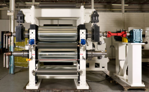
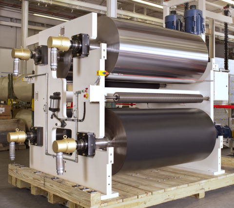
A method in which a web, passing around an elastomer rubber covered impression roll is coated in a nip formed with an engraved applicator roll. As shown in Figure 1, the rolls rotate at the same speed, with the coating transfer to the web dependent upon its release from the engraved cells. Although gravure coating is used over a wide viscosity range, it is most popular for applying low viscosity, thin film coatings at high speeds.

The coating is applied to the applicator roll either from a pan in which the roll is immersed or from an enclosed applicator feed system. In most instances, excess coating is removed from the land surfaces by a flexible doctor blade pressing against the rotating roll. The choice of the feed system is often speed and process related. At applicator or roll speeds up to 3.75 meters per second, a pan design is often used particularly for low viscosity coatings. As speed and viscosity increase, using an enclosed feed system will force the coating into the engraved cells, minimizing air entrapment and foaming. Enclosed feeds are also used to minimize evaporative losses when solvent coatings are applied.
Factors that affect the coating weight and quality are:
- The applicator roll pattern, cell volume and shape
- The thickness and hardness (durometer) of the impression roll covering
- The nip pressure developed between the impression and applicator rolls
- The type, position and operating pressure of the doctor blade system against the applicator roll
- The viscosity and flow properties of the coating
- The type of web being coated and its finish
- The speed of the operation and the atmospheric conditions at the time of coating
For a given coating, whose properties remain constant, and a particular web, direct gravure coating is a straightforward concept. One will continuously apply the same amount of coating to a web through a broad speed range, as long as the doctor blade and nip settings remain the same.
One of the most important factors is the selection of the applicator roll pattern and cell volume. For a given coat weight, selection is based upon the solids content of the coating, its viscosity, and its flow characteristics. Direct gravure coating is versatile, applying from low-solids/low-viscosity coatings, to higher viscosity coatings up to 100% solids. Figure 2 shows typical pyramid, quad, and tri-helix cell patterns that represent different volumes.
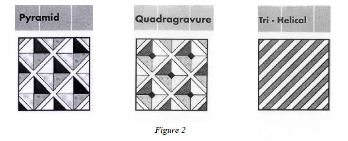
It is important to recognize that only a percentage of the volume of coating in the engraved cells is transferred. This usually varies from 50% to 80%. Pyramid cells often release the lowest amount, while tri-helix patterns release the highest. One can increase the release characteristics by applying an electrostatic assist charge to the impression roll. It is possible to select the same pyramid or quad pattern number with a different depth, depositing more or less coating material. The choice of cell structure is dependent upon the coating viscosity and flow parameters. One might select a pyramid or quad cell engraving for a low solid, low viscosity coating, rather than a tri-helix pattern, since the discrete cells retain the coating in cup like fashion. Once the pattern is selected, the cell volume can be calculated.
The thickness and hardness (durometer) of the elastomer rubber covering on the impression roll also plays a role in the coat weight application. A thicker, softer covering is more deformable than a thinner, harder covering. Hence, more coating is applied by the hydraulic action at the nip in the former condition. For thin rubber coverings, where the ratio of covering thickness to impression roll radius is 0.1 or less, flow rates are significantly reduced, due to less roll deformation.
Doctoring of the applicator roll is usually done by using a flexible steel blade. There are applications where a doctoring roll can be used, but the hydraulic force developed at the nip of the applicator and rubber covered doctoring roll usually results in significant coating carry over onto the web. The thickness and length of a doctor blade, the force applied to it and its position on the applicator roll, determine the amount of coating wiped from the roll surface. The land area of the engraved pattern also plays a role in the coating removal process. A large land surface with high cell volume is most conducive to a cleaner wipe.
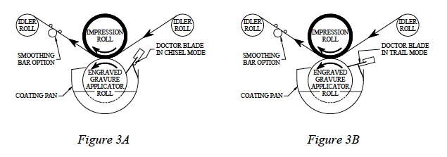
The doctor blade can be placed in a “chisel” mode, (Figure 3A), where the blade tip opposes the direction of travel of the roll, or in a “trail” mode, (Figure 3B), where the tip points in the direction of travel of the roll. Properly used, the “chisel” mode provides the maximum wipe of the applicator roll, since the probability of blade lifting is minimal and shearing force is high. In the “trail” mode, depending upon the blade thickness and length, lifting can occur due to the hydraulic forces that develop from the action of the coating fluid against the underside of the blade. Improperly used, either mode of doctoring can result in coating carry over due to blade flexure.
Enclosed, chambered coating applicators feature a combination of powered coating feed and doctor blade metering. Coating compound is pumped through the chamber enclosure, via ports designed to optimize the coating distribution. Doctor blades are placed at the top and bottom of the applicator, affording total enclosure control of the system. Resilient end cheeks conform to the applicator roll surface. The unit is mechanically or pneumatically loaded against the roll. In pneumatic systems, compensation for blade wear is automatic. By enclosing the coating compound in a feed applicator, evaporation of solvents is prevented, making this method a favorite for emission controlled applications. Flushing systems, complete with waste management controls, are also available.
When higher viscosity coatings are applied, the coating may not “flow out”, leaving the web imprinted with a pattern of coating deposits from the applicator roll. By the use of a driven smoothing bar, as shown in Figure 1, placed against the coated side of the web just after the nip, the peaks of coating material are leveled, resulting in a more uniform coating surface. Tension control of the web at the smoothing bar is important. It is achieved by placing adjustable support bars pressing against the back side of the web, one before and one after the smoothing bar. The position of the support bars controls the web wrap around the smoothing bar. The smoothing bar is usually driven at a slow speed, opposite the direction of travel of the web.
While the major advantage of direct gravure coating is the ability to consistently apply the same amount of coating to a web under constant operating conditions, there is little opportunity to make significant coat weight changes without using a different applicator roll. Using doctoring techniques, where excess coating is allowed to remain on the lands above the applicator roll engraved surface, some weight can be added without compromising process control.
###
*That concludes part 1 of our 3 part series, “Principles and Uses of Roll Coating Equipment”! Check back soon for part 2.*