The following is part two of a series of 3 blogs that will go through a white paper written by New Era Converting Machinery’s Bob Pasquale and Tom Lombardo. The white paper is titled “Design Considerations in Solvent Vs. Water Based Coating Equipment.”
Part 1 offered an overview of the entire paper and what to expect in coming blogs. Part 2 will discuss how to design equipment to address solvent flammability and operator health. Part 3 finishes with design considerations for emissions, what drying equipment differentiation there is between the two, and how to resist corrosion, as well as a short conclusion.
—–
PART 2: Addressing Solvent Flammability and Operator Health Through Equipment Design
EQUIPMENT DESIGN TO ADDRESS SOLVENT FLAMMABILITY:
Because of the flammability of solvent vapors, the use of spark generating electrical components is a major concern. Guidelines have been developed through the years to address and govern the use of these components to assure that they are explosion proof. In the United States these requirements are part of the National Electric Code (NEC). Within this code the electrical requirements are defined based on several factors and are broken down into three categories: Class, Group and Division. Locations that may have flammable gases or vapors present in the air in quantities that are high enough to support an explosion or ignition are considered Class I. The Group is rated on a letter scale between A and D, based on the type of explosive mixture that may be present. The solvents that are typically used in coatings fall into Group D. Regarding Division, areas that have hazardous concentrations of gases or vapors present in the air on a continuous, intermittent or periodical basis under normal use are considered Division I locations. Areas adjacent to the Division I locations in which hazardous concentrations of gases or vapors may occasionally be present in the air are considered Division II.
The NEC defines the size and extent of the Class I, Group D, Division I and Division II areas based on the proximity to an open source of solvent. Sketch #1 (below) gives a graphical representation of these areas with respect to the open source of solvent.
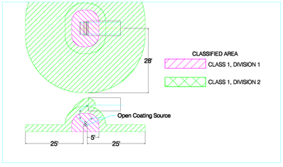
The open source of the solvent will vary based on the coating application method. For a die coater the coating application point is considered the open source. For a pan fed coater (gravure, saturation, four roll reverse roll, etc.) the entire pan would be considered the open source. The proximity of the equipment around the coater will determine its electrical requirements in accordance with the above sketch. Additional consideration needs to be given to how the solvent based coating is delivered to the coater. Any areas in the delivery system that would openly expose the solvent to the air would also be considered a source and would fall under the same classification and requirements.
All equipment outside the area outlined in the above sketch would be considered in a non-hazardous (General Purpose) environment and would not be subject to any special electrical requirements.
Different electrical requirements apply to each of the three above mentioned locations (non-hazardous; Class I, Group D, Division I; and Class I, Group D, Division II). These electrical requirements can be divided into two subsets, namely the electrical devices and the wiring.
Regarding the devices, these can be of one of four designs: Explosion Proof (XP), Intrinsically Safe (IS), Purged or General Purpose. An Explosion Proof (XP) device is one that is designed so that any explosion that occurs inside the device’s housing will be contained and will prevent sparks from inside that device’s housing from igniting vapors or gases in the air outside of it. In order to be rated as Explosion Proof, devices must be certified by a national agency (such as Underwriters Laboratories or Factory Mutual). An Intrinsically Safe (IS) device is one whose electrical energy usage is below the level required to set off an explosion within a given hazardous area. These devices are also incapable of storing large amounts of energy which might spark an explosion when discharged. An Air Purged device is one where fresh air is delivered to the device to prevent any vapors or gases from getting to the electrical components. Air Purged systems are kept under positive pressure when operating to prevent the vapors and gases from contacting the devices electrical components. A General Purpose device is one that has no special design for preventing contact with or ignition of vapors or gases.
Chart #1 (below) list several different electrical devices and the design that can be used in each of the three previously discussed environments. In general, if the device can create an arc, it must be XP, IS or air purged in either the Division I or Division II areas. This includes switches, relays, limit switches, DC brushes and tachometer bushes. Devices that cannot create an arc must be XP, IS or air purged in Division I areas but can be of general purpose design in Division II areas. This includes any winding or coil type device such as 3 phase A.C. induction motors, solenoids and brakes.
| ENVIRONMENT | |||
| DEVICE | NON-HAZARDOUS | CLASS I, GROUP D, DIVISION II | CLASS I, GROUP D, DIVISION I |
| AC Motors | open, drip-proof or TENV | open, drip-proof or TENV* | XP |
| Electric Brakes | Standard/General Purpose | Standard/General Purpose* | XP |
| Solenoids and Valves | Standard/General Purpose | Standard/General Purpose* | XP, IS or in an XP or purged housing |
| Electric Clutches | Standard/General Purpose | Standard/General Purpose* | XP or purged |
| Force Transducers | Standard/General Purpose | Standard/General Purpose*** | XP or IS |
| Junction Boxes | Standard/General Purpose | Standard/General Purpose⁺ | XP |
| DC Motors | Standard/General Purpose | XP | XP |
| DC Tachometers | Standard/General Purpose | XP | XP |
| Limit Switches | Standard/General Purpose | XP or IS | XP or IS |
| Pushbuttons | Standard/General Purpose | XP or IS | XP or IS |
| Relays | Standard/General Purpose | Housed in an XP or purged encl. | Housed in an XP or purged encl. |
| Slip Rings | Standard/General Purpose | Purged | Purged |
| Encoders | Standard/General Purpose | Standard* | XP |
| HMIs | Standard/General Purpose | Standard** | Purged |
| ⁺ = provided the device is rated as per NEC 501.10 | |||
| * = if device is approved for use in Class I, Group D, Division II environment: if not, then it must be XP | |||
| ** = if device is approved for use in Class I, Group D, Division II environment: if not, then it must be purged | |||
| *** = must be wired to an IS barrier or a Class 1, Group D, Division II device | |||
All wiring in the Class I, Group D, Division I environment must be designed to meet Explosion Proof requirements. This wiring must be totally enclosed in appropriately rated conduit and fittings. All conduits must be sealed within 18” of both the hazardous area boundary and the device. The exception to the above is when using intrinsically safe devices in the Class I, Group D, Division I area, for which non-explosion proof conduits and fittings can be used as long as seal offs are provided at the hazardous area boundary and the IS wiring is isolated from all other wiring.
In the Class I, Group D, Division II area general purpose conduit and fittings can be used. However, seals are required at each spark making device.
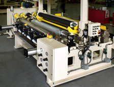
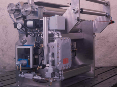
In general, devices that are XP are much more costly than those that are general purpose. Air purge systems are also costly and require additional electrical devices in order to monitor them. With regarding to wiring, the material required in the hazardous area is more costly and the amount of labor to perform the wiring is significantly higher than that for a non-hazardous area.
In addition to electrical components and wiring being a source for ignition of gases and/or vapors, one needs to be concerned about static electricity in the area. It is extremely important that static elimination equipment be incorporated into the design of the system to prevent potential sparks from static in the web. It is also important that all personnel and hardware in the area is properly grounded to prevent sparks. Finally, an area often overlooked, one must be careful that portable electric devices (laptops, cellphones, etc.) are restricted in the hazardous areas.
One of the major advantages of a water based coating system is that there is no need for special devices or wiring since there are no flammable vapors present. Therefore, all devices and wiring can be provided for use in a general purpose environment.
DESIGN OF THE EQUIPMENT FOR OPERATOR HEALTH:
As indicated earlier, exposure to solvents has short term health effects such as irritation of the skin, eyes, nose and throat, headaches and nausea and long term effects such as damage to the liver, kidneys, lungs and central nervous system. Therefore, it is extremely important that the equipment be designed to minimize the exposure of operators to the solvents. There are several ways that this can be accomplished.
The use of personal protection equipment (glasses, gloves, respirators, etc.) is the most basic form. However, the use of this equipment can reduce the operators’ ability to perform the required tasks associated with the operation of the coating equipment.
The use of ventilation equipment local to the coater is often used to reduce the operators’ exposure to the solvent vapors and gases. However, this too has its disadvantages. In many operations this is attempted by placing exhaust hoods over the coater. There are several issues with this approach. First, since the solvent vapors are typically heavier than air, an overhead hood is typically ineffective at capturing them. Second, if the hood is strong enough to capture some of the solvent vapors, it often drags the vapors past the operators’ face. An alternative solution to this is to provide the ventilation at the bottom of the coater, allowing for a better opportunity to capture the heavier than air solvent vapors. However, this solution doesn’t capture all of the solvent vapors and may not be enough to reduce the operators’ exposure to the vapors.
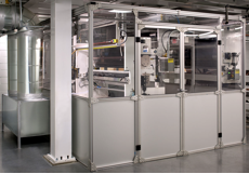
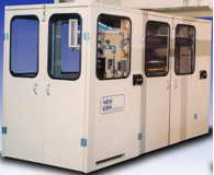
Today’s modern solvent coating systems typically include an exhausted enclosure around the coating station to protect the operator and capture the solvents. These enclosures are typically of one of three designs. The first is an “area type” enclosure that surrounds both the coater and the operator area around it. These enclosures require the operator to enter them in order to make adjustments to the coater, therefore still requiring the use of personal protection equipment when doing such. The second type of enclosure is the “close fitting type”, designed to fit tightly around the coater but requires the operator to open doors/hatches to make adjustments. While this design certainly limits the operators’ exposure during operation, it doesn’t eliminate it during adjustments. This exposure can be reduced by using a multi-speed exhaust fan that increases in capacity when the access doors/hatches are open in order to increase the ability to capture the vapors/gases. The third type of enclosure is one that is designed to fit closely around the coater, with the controls required for adjusting located outside the enclosure. In this case, operator exposure to the vapors/gases is all but eliminated during operation. The only time that access is required inside the enclosure is during maintenance, during which the solvent do not need to be present and therefore neither are the vapors/gases.
The use of coater enclosures offers an additional distinct advantage. With the inclusion of the enclosure around the solvent source, the previously described electrical classifications are redefined, with the Class I, Group D, Division I area being limited to inside the enclosure and the Class I, Group D, Division II areas being related to the location of the enclosure openings. Sketch #2 (below) gives a graphic representation of these areas when a coater enclosure is used.
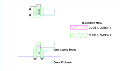
There are certain design features that need to be applied to these enclosures including the use of equipment to monitor the solvent levels within the enclosure (LFL monitoring equipment), the inclusion of adequate explosion relief panels/surfaces and the use of safety glass for viewing windows.
When using water based coatings, the need to protect the operator from harmful vapors/gases is minimized. Though the operators still should wear certain personal protection equipment, the amount required is greatly reduced. Also, the need for ventilation equipment and/or coater enclosures is greatly reduced. This allows for the operation and maintenance of the equipment to be much less cumbersome.
###
*Check back soon for the 3rd and final part!*



 Downloadable Brochures in PDF Format