The following is the third part in a series of 4 blogs that will go through a white paper written by New Era Converting Machinery’s Bob Pasquale. The white paper is titled “Lamination System Application and Design Considerations.”
Part 1 offered an abstract and introduction to the blog series, as well as an overview of Wet Bond Lamination. Part 2 went through Dry Bond Lamination and Thermal Lamination. Part 3 will discuss a few design considerations, including Roll Design, Nip Pressure Control, and Gap Control. Part 4 will wrap the series up, finishing with design considerations including the Roll Drive, Alignment, Web Handling, and Guarding and then offer a brief Conclusion.
—–
DESIGN CONSIDERATIONS IN A LAMINATOR:
The design of the laminating section is critical to the success of the process. There are several factors that need to be addressed in the design, some of which are common for all laminating processes and some that are unique to each. As indicated previously, in all cases, it is typical that the webs are combined at a lamination nip formed by two rolls that are either pressing together or have a controlled gap between them.
ROLL DESIGN:
Several factors need to be considered in designing the rolls that will be used on the laminator. As stated earlier, it is typical that one roll features a hard surface such as chrome plated steel, with the other featuring a resilient surface such as rubber. This combination allows the rolls to be pressed together to generate the required force to combine the webs without damaging the surface of the rolls (particularly a concern in the area where the rolls contact outside the width of the web and when the rolls contact during web breaks).
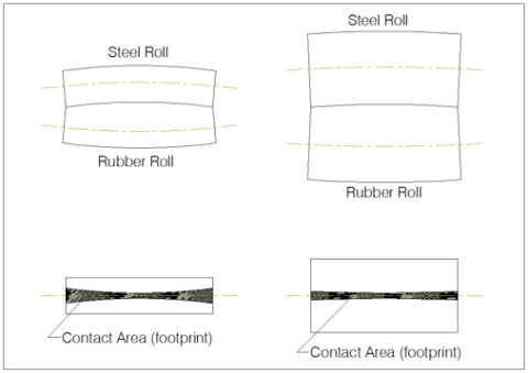
The rolls must be of sufficient diameter to support the process. This is of particular concern for applications where the pressure between the rolls is high, since the greater the pressure between them, the greater the roll deflection and the greater the bow in the middle. Since one roll is rubber covered, this bowing shows up in the “footprint” of the rubber roll. As the pressure is increased between the rolls, the rubber in the area of contact compresses, resulting in the rubber conforming to match the surface of the mating steel roll. As the deflection/bow between the rolls increases this conforming (footprint) becomes uneven, with a narrower contact area in the middle than on the edges. As a result of the uneven footprint, the force between the rolls varies across the width which can affect the lamination bond’s evenness. Additionally, the difference in compression results in a difference in rubber roll diameter at the area of contact which results in a variation in the local surface speed. This variation in speed can result in wrinkles and/or stresses in the web which can affect the lamination quality. As the roll’s diameter is increased so is its stiffness thereby reducing the defection and bow and therefore the variation in footprint (See Figure 6). There are other ways to address the concern over uneven footprint, all of which have certain drawbacks. These include grinding a crown in the rubber roll’s surface to compensate for the deflection (which works well when operating at a specific nip pressure but can have adverse effects when the pressure is changed), skewing the rolls with respect to each other (which can negate the effect of footprint but can also introduce wrinkles and stresses in the webs), and bending of the rolls (which can be used to compensate for the deflection but is a very expensive and complex system).

It is often typical, particularly in dry bond and thermal lamination, that the steel roll used in the laminating nip assembly is heated to allow for heating of the web. This heating can be done in several ways including internal electric heating or, more typically, by passing a heating fluid such as steam, water or oil through the roll. What is critical is that the temperature profile across the roll be uniform so that heating across the width of the web is uniform. Though this is fairly easy to address in internally electrically heated rolls, the internal design of the fluid heated roll is critical. The properly designed fluid heat roll features a double shell construction with spiral passages between the shells so that the flow of the fluid is controlled. The control of the path, volume and speed of the fluid passing through the channels formed between the shells of the roll is critical to maintain a uniform temperature. The diameter of the steel roll is critical in these types of applications since sufficient web to roll contact distance/time is required to heat the web to the desired temperature prior to lamination.
The accuracy of the rolls’ diameter (concentricity and TIR) is also a factor that needs to be considered since variations in the diameter can have adverse effects on the lamination process. The greater the variation in the rolls’ diameter the greater the local speed and pressure changes, both of which can affect the lamination process.
Another consideration in the design of the rolls is the consistency in their surface finish. Variations potentially affect the laminated product since surface irregularities can result in marks or blemish in the product.
The selection of the rubber roll’s rubber material and hardness is a significant topic which could be addressed as an entirely separate topic. In general terms it is important to match the selection of rubber material and hardness with the particular application, taking into consideration the pressure and temperature requirements as well as the chemicals/materials that the rubber will be exposed to. Regarding temperature, one must consider if the core of the rubber roll needs to be designed for the internal passage of fluid. For high temperature applications it may be necessary to internally cool the steel core so that the material used to bond the rubber to the steel doesn’t fail. For other moderate temperature applications one might elect to heat the core.
As a final comment regarding the rolls, until now we have discussed lamination nips that involve one steel and one rubber roll. There are instances where two steel or two rubber rolls are used for the lamination nip. These cases typically involve special conditions. An example of this is the dry bond lamination of two thick webs that both require preheating, in which case a nip featuring two steel rolls can be used. Another example is when dry bond laminating a film to a thick steel or aluminum web, in which case two rubber rolls can be used.
NIP PRESSURE CONTROL:
The pressure required for lamination varies based on the specific product and application. Therefore, it becomes critical to be able to adjust and set the pressure of the laminating nip. It is typical that one of the two nip rolls, usually the rubber roll, is mounted in bearing assemblies that are held either in slides or pivot arms that allow the roll to be loaded against the other roll through a set of cylinders.
The sizing of the cylinders (bore) is based on the forces required between the rolls for the lamination process. As part of this sizing process, one must consider the fluid medium that is to be used in the cylinders. Using compressed air to pressurize the cylinders offers certain advantages including being easy to work with, easy to handle, and typically readily available in an industrial environment but being limited in its maximum working pressure. Using hydraulics offers the advantage of higher working pressures and more accurate pressure control, but often requires the purchase of a separate pumping and delivery system and can result in maintenance and housekeeping issues.
It is typical to use the previously described cylinders to retract the rolls from each other for threading, clean up maintenance and, most importantly, safety purposes. It is good practice to have the rolls retract a minimum of 4” from each other to meet the safety requirements, with the controls being interlocked with the machine’s safety system so that the roll retracts in emergency situations. The system should also be designed so that the roll retracts on loss of air/hydraulic pressure or electricity.
Regulating equipment is required to allow for the setting of the pressure. This setting can be performed in one of two ways. In some applications, particularly those where there is minimal need to change the pressure, the pressure can be adjusted manually at the regulators. For other applications, particularly those where the pressure needs to be changed often, it can be done from an operator screen, where a pressure value is inputted which, through the machine’s control system, adjusts the regulators pressure by using a device such as an I/P convertor. In either case, one must decide if the system design allows for the pressure for both cylinders to be adjusted by one regulator or if independent regulating equipment is required for each cylinders with several factors influencing this decision including the width of the process and the balance of the nip roll (does one side have a drive or rotary joint connection that may make it heavier than the other).
GAP CONTROL:
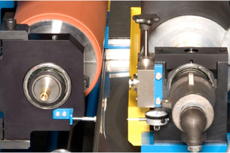
For certain applications it is important to be able to position the surface of the two nip rolls in close proximity to each other without touching. An example of this is during wet bond laminating, where nipping the rolls together may result in the coating being forced into the porous web or out from between the web layers. Another example is when laminating thick webs and coatings that may be damaged by over compression. In these instances it is typical to locate an adjustable gap control device such as a taper wedge or gear based assembly between the nip rolls’ bearing housings (See Figure 7). When the nip roll’s cylinders are extended, the bearing housings contact the gap control device. As the gap control device is adjusted, so too is the gap between the rolls. It is typical that a gap control device be located between the bearing housings on each side of the machine. These two (2) gap control units can either be independently adjusted or can be controlled from a single input. The ability to adjust the gap can be done manually or automatically, and can be performed locally or remotely from a location such as an operator input screen. In the manual system it is typical and desired to have local readout devices that can indicate the gap setting (See Figure 7). In the automatic system it is common to have electronic measuring devices that sense the gap and feedback to the system for closed loop gap control. It is also common that the gap adjusters be designed so that when fully retracted the rolls contact each other, allowing for the nip to be used as in a pressure mode.

*That concludes part 3 of our 4 part blog series, “Lamination System Application and Design Considerations” – check back soon for part 4, or click here to go back and read part 1 or click here to read part 2!*


 Downloadable Brochures in PDF Format