The following is the fourth and final part in a series of 4 blogs that have gone through a white paper written by New Era Converting Machinery’s Bob Pasquale. The white paper is titled “Lamination System Application and Design Considerations.”
Part 1 offered an abstract and introduction to the blog series, as well as an overview of Wet Bond Lamination. Part 2 went through Dry Bond Lamination and Thermal Lamination. Part 3 discussed a few design considerations, including Roll Design, Nip Pressure Control, and Gap Control. Part 4 will wrap the series up, finishing with design considerations including the Roll Drive, Alignment, Web Handling, and Guarding and then offer a brief Conclusion.
—–
DESIGN CONSIDERATIONS IN A LAMINATOR (continued):
ROLL DRIVE:
Though it is typical to drive the rolls at the laminating nip, the question of how to drive the rolls and how to control the drive(s) requires consideration. In most laminating nips it is common practice to drive the steel roll, particularly if it is larger in diameter than the rubber roll, is mounted in a fixed position, and if the primary web has significant wrap around it.
In order to assure proper web handling the control of this drive can vary depending on the design of the laminating system. For a typical dry bond laminator, like that shown in figure 3, the laminator steel roll drive is typically tension regulated, with its speed controlled to maintain web tension in the primary web based on a feedback signal from a tension sensing roll located in the web path prior to the laminating roll. In other applications the best drive configuration may be to have the laminating steel roll serve as the lead drive at which the line speed is set, with the other driven sections being tension regulated with respect to it. An example of this would be for the thermal bond laminator shown in figure 5.
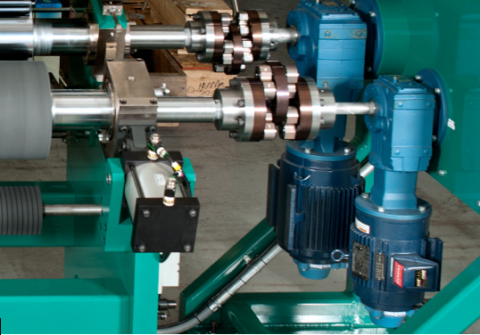
Also to be considered is the need to drive both rolls at the laminating nip. Depending on the nature of the laminating process, this may be required for proper web handling and lamination. An example of this is when laminating thick webs in the gap mode, particularly if one or more of the webs is extensible. In this case trying to rotate the rubber roll through the web material can result in adding stresses to the web(s) which may show themselves in the form of wrinkles or curl in the product. In cases such as this it is typical to drive each of the laminating rolls with independent drives, with the main roll being controlled as previously discussed and the other roll being driven either in a speed mode, following line speed, or in a torque mode, where the drive is used to reduce the drag of the roll. Since the nip roll’s position is adjustable, it becomes necessary to be able to drive the roll throughout its range of motion. This can be accomplished either by mounting the motor and transmission assembly on the moving bearing housing assembly or interconnecting a fixed position motor to the moving roll through an adjustable transmission assembly (See Figure 8).

ALIGNMENT:
The alignment of the laminating rolls to each other as well as to the balance of the machine is critical for proper lamination. The laminating section not being properly aligned with respect to the processing line could result in stresses being introduced to either or both of the webs during lamination, which may show up as wrinkles, stretch lines, or curl in the product. If one roll is not properly aligned with respect to the other roll, in addition to the same stress related issues occurring, improper lamination may result from uneven/non-uniform nip pressure across the width of the rolls.
WEB HANDLING:
The handling of the webs into and out of the laminating section is critical to proper lamination. Improper web handling can result in flaws in the product and/or poor lamination.
Good tension control of the webs entering the lamination nip is of extreme importance. If either web is under tensioned, issues like wrinkle lines and fold-overs may occur in the web and show in the finished product. Too much tension may result in issues such as stretch lines in the web which may show up in the product. Additionally, too much tension in one of the webs may result in web curl in the finished product.
Since wrinkles, fold-overs and other irregularities that are present in the webs entering the lamination point can show up in the final product it is typical to include spreading rolls in the web paths into the laminating assembly to help eliminate these occurrences and present the webs to the laminating section as flat and smooth as possible. These rolls can be in many forms including bow rolls, rubber rolls with herringbone patterns, and rubber cord type spreader rolls, with the roll selection being based on factors such as web material, speed, tension and temperature.
The angle at which the webs are introduced to each other at the laminating nip is also important to successful lamination. In a typical laminator it is important that the webs do not contact each other prior to the lamination point, which would result in potential flaws in the laminated product such as wrinkles and air entrapment between the layers of the web. It is also typically important that the two webs approach the lamination point with a large angle between them so that air doesn’t get entrained between them during the lamination process which could result in flaws in the product.
Proper tension control of the web as it exits the lamination point is also important, especially in processes such as wet bond lamination where the bond strength between the layers has not yet formed and can be damaged by improper tension, resulting in poor final product bond.
GUARDING:
Of extreme importance is the guarding of the laminating section for operator safety. The guards must be designed to restrict access to the hazardous areas such as in-running nip rolls, crush points (such as between bearing housings), heated surfaces, and drive transmission assemblies. Of extreme importance is the guarding of the laminating section for operator safety. The guards must be designed to restrict access to the hazardous areas such as in-running nip rolls, crush points (such as between bearing housings), heated surfaces, and drive transmission assemblies. These guards need to allow for the treading and maintaining of the equipment without compromising the operators’ safety.
CONCLUSIONS:
As we have shown, there are several different ways to laminate webs together, with the choice of the proper system typically dependent on the products that are being combined. Once the appropriate system has been selected, there are several critical design features of the laminator that need to be addressed to assure successful lamination of the product.
BIOGRAPHY:
Bob Pasquale is one of the founders and principals of New Era Converting Machinery, where he serves as President. He holds a degree in Mechanical Engineering from Stevens Institute of Technology and has worked in the web converting industry since 1985. He is the holder of several patents in the industry. Bob can be reached at bob.pasquale@neweraconverting.com.
REFERENCES:
Pasquale, John A. III, “Laminating.” Modern Plastics Encyclopedia. 1992
Satas, Donatas, Web Processing and Converting Technology and Equipment, New York, New York: Van Nostrand Reinhold Company, 1984
Weiss, Herbert L. Coating and Laminating Machines, Milwaukee, Wisconsin: Converting Technology Company, 1977
###
*That concludes our 4 part blog series, “Lamination System Application and Design Considerations” – thanks for reading! If you missed the first three, click here to go back and read part 1, click here to read part 2, or click here to read part 3!*


 Downloadable Brochures in PDF Format