The following is part two of a series of 4 blogs that will go through a white paper written by New Era Converting Machinery’s Bob Pasquale. The white paper is titled “Selecting an Unwind and Unwind Splicer System.”
Part 1 offered an overview of the entire paper and what to expect in coming blogs. Part 2 will discuss the holding of the web rolls when unwinding and tension control of the unwinding material. Part 3 continues with the guiding of the web as it exits the unwind, how the end of the expiring roll’s web will be spliced to the beginning of the new roll’s web, and how the expiring roll’s web will be cut. Finally, part 4 will detail the number of unwind positions, offer a comparison of roll to roll versus continuous unwinding, and finish with a brief conclusion.
—–
PART 2: Holding Web Rolls When Unwinding and Tension Control of Unwinding Material
HOLDING OF THE WEB ROLLS WHEN UNWINDING:
The biggest consideration when discussing how to hold a roll of web in an unwind is whether a shaft is to be used. In a “shafted” unwind, a bar is placed inside the web roll’s core to both support it and interface it with the unwind. This bar is typically locked to the core to prevent slip between the two, with the locking being performed in one of several manors including driving tapered cones into the core or, more commonly, by employing a shaft that pneumatically expands to lock the two together. The shaft typically features ends that are designed to interface with holders mounted on the unwind, allowing the web roll to be supported. These holders allow for the rotation of the roll of material so the web can be paid out. A typical shafted unwind is shown in Figure 1.
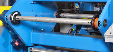
There are several advantages to a shafted unwind including lower equipment cost, lower maintenance and, typically, a smaller equipment footprint. However, there are disadvantages to this design, with the major one being the need to handle the shafts, particularly a problem on wider webs and bigger core diameters, where the weight of the shaft becomes a safety issue.
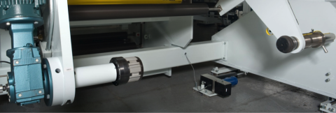
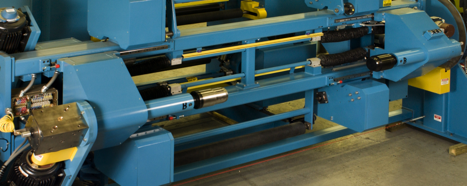
To address the issues associated with the handling of shafts, many unwinds are built as “shaft-less” units, with the web roll being held by unwind mounted supports that are inserted into the ends of the web rolls’ cores and are designed to prevent slip between them and the core. Figure 2 shows a system designed for holding cores that are of a single width. In this case a pneumatic cylinder is used to insert the holders into the core. Though this type of system, which is typically slightly more costly than a shafted unwind and usually results in a wider assembly, offers the advantage of eliminating the handling of shafts, it is limited to a single width core. Figure 3 shows a system designed for the shaft-less holding of varying width cores. In this arrangement the side frames are adjustable, allowing for greater travel and therefore the ability of the holders to be inserted into cores of various lengths. This system offers the obvious advantages of being able to interface with multiple core widths without the need to handle an airshaft. However, this system is more expensive than the other designs and typically results in a much wider machine section.
TENSION CONTROL OF THE UNWINDING MATERIAL:
There are several decisions that need to be made regarding tension control of the unwind. For starters, one needs to consider if the system should include closed loop constant tension control. On a center unwind tension is applied by using a device to impart a drag on the shaft/spindle that holds the web roll. As the diameter of the unwinding roll changes so does the force on the web and therefore the tension that the web sees from the imparted drag. In the most basic of systems, the drag is kept constant, ignoring the change in web tension that occurs as the diameter changes. This is the most inexpensive way to provide the system but represents the least amount of control since the web tension continuously varies. As a step up from this, one can use a device to sense the unwinding roll’s diameter so that the drag force can be adjusted to obtain a constant tension.
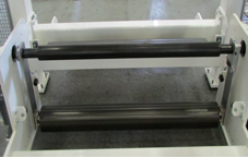
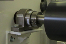
Though this system, which is more costly than the previously described arrangement, does allow for adjustments in the force of the drag device in an effort to maintain a constant tension, it does not have a way to control it based on feedback from a tension measuring device. A closed loop measuring and control system, though more costly, allows for optimized constant tension control based on true feedback of the web tension. This type of system can feature a variety of hardware including a roll mounted on a pair of electronic force transducers (Figure 4) and/or a dancer assembly (Figure 5). The use of the force transducers offers certain advantages including minimal space and lower cost when compared to a dancer but does not offer the dancers ability to adsorb sudden changes in tension that may result from items such as out of round rolls or automatic splicing.
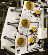
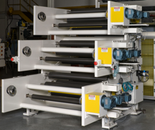
In addition to the above decisions regarding tension control, one must decide what type of device should be used to apply the drag force. Typically this can be done through the use of either a brake (Figure 6) or a motor/drive set (Figure 7). Brakes offer certain advantages over motor/drive systems. They are typically less costly to purchase, install and operate, are easy to operate and require minimal maintenance. Pneumatic brakes are excellent for use in hazardous rated electrical areas (since they are non-sparking) as long as the heat they generate remains below the allowed levels. However, there are disadvantages to using a brake. They can be limited in their total tension range, may not work well at very low tensions since the lowest drag of the brake may exceed the tension requirements, may not work well with damaged rolls where the forces required to overcome the damage may exceed the tension force and often have problems during roll acceleration, where the forces to accelerate the roll can exceed the web tension. They also do not lend themselves well to applications where the roll of material needs to be accelerated prior to unwinding, such as in automatic splicing systems. The use of a motor/drive to control the tension overcomes the above issues. However, this too has its drawbacks, including being more costly, especially in a hazardous environment, requiring more maintenance and not working well in low speed applications due to issues with reflected inertia.
###
*Check back soon for the next blog in the series, or go back and read the first!*


 Downloadable Brochures in PDF Format