The following is the final part in a series of 4 blogs that has gone through a white paper written by New Era Converting Machinery’s Bob Pasquale. The white paper is titled “Selecting an Unwind and Unwind Splicer System.”
Part 1 offered an overview of the entire paper and what to expect in coming blogs. Part 2 discussed the holding of the web rolls when unwinding and tension control of the unwinding material. Part 3 continued with the guiding of the web as it exits the unwind, how the end of the expiring roll’s web will be spliced to the beginning of the new roll’s web, and how the expiring roll’s web will be cut. Finally, part 4 will detail the number of unwind positions, offer a comparison of roll to roll versus continuous unwinding, and finish with a brief conclusion.
—–
PART 4: Number of Unwind Positions and Roll to Roll Versus Continuous Unwinding
NUMBER OF UNWIND POSITIONS:
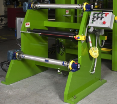
Of major consideration is the number of unwind positions that are included with the unwind. In simplest form, an unwind can feature a single position for holding material rolls. The design of this type of unwind can vary from a simple and relatively inexpensive frame with chucks for holding an unwind shaft (Figure 16) which can be loaded via a system such as a hoist, to a more costly system such as a floor pick up unit, designed for self-loading of a web roll from the floor. With either of these systems, or any other single position unwind, a significant amount of time is required to safely load and splice a new roll of web material when the running roll expires, requiring the process line that is being fed by the unwind to be stopped.
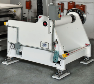
In an effort to reduce the time required to change rolls of web, one can incorporate a two position unwind (Figure 17), allowing for a new roll of web to be loaded and prepared for splicing in one unwind position while the web is running from the other unwind position, thereby reducing the time required to splice the new web onto the expiring one. However, even with this design, the safe splicing of the web requires that the process line be stopped.
ROLL TO ROLL VERSUS CONTINUOUS UNWINDING:
For many operations it is not practical to stop the process line to allow for the unwind rolls to be changed and/or spliced. In these applications the unwind system needs to be designed to allow for the continuous feeding of web to the process. This can be accomplished in one of two ways, either by providing a system that allows for the web to be fed to the process continuously while the unwind is stopped or by providing a system that allows for the splicing of the new web to the old without stopping the unwind.
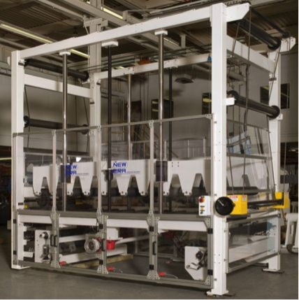
In the first of these systems, a section such as a “J” box, conveyor or, most typically, a web accumulator (Figure 18) is incorporated in the process line just after the unwind. In this design excess web that has been stored in the “J” box, conveyor or accumulator is fed to the process while the unwind is stopped for splicing. This type of system has its advantages including allowing for time consuming splice methods such as sewing or welding to be performed without stopping the process. However, there are drawbacks to these types of systems, including requiring a significant number of rolls to contact and possibly damage the web. Additionally, these types of systems do not lend themselves well to high speed applications because of the storage required to feed the process.
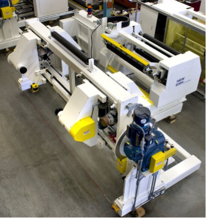
In the second of these systems, the unwind is designed to allow for splicing of the leading end of the new roll to the tail end of the expiring roll without stopping the unwind. This type of system can take one of several forms but most typically features a turret unwind with an automatic splicing and cutting system (Figure 19). Here the new roll of web is loaded into the non-active unwind position and prepared for splicing to the unwinding roll of material, including cutting the leading edge of the new roll’s web and applying tape or adhesive. At the appropriate time, either controlled by the operator or performed automatically, the turret indexes, bringing the new roll into the splice position. The leading edge of the new roll of material (where the tape or glue has been previously applied) is brought into contact with the running web from the expiring roll, sticking the two together, followed by the running web from the expiring roll being cut between the expiring roll’s unwind position and point of contact of the two webs, allowing for the splicing of the leading edge of the new roll to the expiring roll’s end without stopping the unwind. This type of system has several advantages including allowing for the automatic splicing of new rolls at high speeds. However, there are certain drawbacks to such a system including being limited to lap type splices and only applying to those splices that use tape/adhesive.
CONCLUSION:
In conclusion, there are many different design considerations and decisions that need to be made when matching an unwind to a web process. Care needs to be taken to assure that the system is designed to maximize the operation of the process.
BIOGRAPHY:
Bob Pasquale is one of the founders and principals of New Era Converting Machinery, where he serves as President. He holds a degree in Mechanical Engineering from Stevens Institute of Technology and has worked in the web converting industry since 1985. He is the holder of several patents in the industry. Bob can be reached at bob.pasquale@neweraconverting.com.
###
*That concludes the final blog in our 4 part series – thanks for reading! If you missed them, go back and read the first, the second and the third now!*



 Downloadable Brochures in PDF Format